Alignment, or in this case suspension alignment, is the final adjustment of the orientation in space of the wheels of a car. In the case of the Fiero, both the front and rear ends require alignment. The easy way to do this is to take the car to an alignment shop. However, some people are not satisfied with the results achieved in this way. Some shops do very good work,some do not, and there is no easy way to pick a good one. Some people like to experiment with other than stock settings for improved handling or some other advantage. Finally, in the course of repairing or replacing certain parts of the car, adjustments will be disturbed. The most common instance of this is replacement of the rear struts. The adjustments need to be restored even if not perfectly just so the car can be driven to an alignment shop. What follows now is a description of the common adjustments, the tools used, and the procedures for making the adjustments. If you intend to try your own alignments read the rest of this carefully and become familiar with it before attempting the real thing. There is a definite learning curve to the procedures and you may have to repeat them several times to get satisfactory results.
Adjustments:
There are three basic adjustments on most cars and the Fiero. These are toe, camber, and caster. These are related to the facts that the tire is held more or less parallel to the direction of travel, more or less square to the road surface, and the turning axis is more or less vertical.
Caster is the inclination of the steering axis in the direction of travel. It is measured in degrees from vertical and if the top is behind the bottom it is called positive. Increasing positive caster increases the tendency of the car to go straight and increases the steering effort. Decreasing positive caster or going to negative caster reduces steering effort but gives the car an "uncertain" feel like it is not sure where it is going. Positive caster also causes extra negative camber when the wheel is turned which can be a good thing. Caster is adjusted on the 84-87 Fieros by moving washers between the front and back of the upper suspension arm, thus moving the upper arm forward or backwards. On the 88 Fiero caster is changed by sliding the mounting bolts of the upper suspension arm in opposite directions, i.e. if the front bolt is moved towards the center of the car and the back bolt is moved out the upper ball joint will be moved forward, decreasing caster. Since the rear suspension is not steered there is no caster adjustment on the rear of the Fiero.
Camber is the inclination of the top of the tire at right angles to the direction of travel (across the car). It is measured in degrees from vertical and if the top of the tire leans out from the car it is called positive. Negative camber increases the side thrust the tire can generate and thus the cornering force it can generate but too much can cause rapid wear of the inside edge of the tire. On the front of 84-87 Fieros with the original ball-joints the only adjustment is to remove the ball-joint and turn it 180 degrees. This will give a camber 1 degree more positive than the original setting. It is possible to get replacement ball-joints with slotted mounting holes which do allow a more useful adjustment range. It is also possible to slot the ball-joint mounting holes in the upper suspension arm to get the same effect but if carried too far the ball-joint will hit the spring. On the 88 Fiero, the camber is changed by sliding the mounting bolts of the upper suspension arm in the same direction, in for more negative or out for more positive. This is a truly miserable system typically found on Fords, as you will learn if you try to align one of these. The rear camber is set with the bolts that hold the bottom of the strut. This can be easy or hard to set depending on the type of bolt and strut.
Toe is the deviation from parallel of a pair of tires in the direction of travel, that is, whether the pair of tires point straight ahead or slightly towards or away from each other. It is measured in inches or more correctly in degrees. A measurement in inches depends on precisely where it is measured on the tire where a measurement in degrees does not but inches are much easier to measure at home. If the front of the tires is closer together than the back it is called toe-in and if the front of the tires is farther apart than the back it is called toe-out. Toe-in results in a tendency to go straight when one tire hits a bump while toe out results in the car swerving. In addition, the front suspension design the 84-87 Fiero is based on (Chevette) is famous for being intolerant of things like wider than stock (5.5 inches) wheels and shimmying to demonstrate its unhappiness. Some of this remains in some Fieros. The general rule for street cars where tire life and over-the-road stability is important is you want enough toe-in that the front suspension cannot go into toe out due to wear or deflection of suspension components such as bushings. The toe on the front of all Fieros is set by turning threaded sleeves on the tie rods on each side. The toe on the rear of 84-87 Fieros is set loosening the lock nut on the arm coming from the drive-train cradle and turning the arm. On 88s there is a sleeve on one of the lower suspension arms. When adjusting these it is important to make the same amount of adjustment on each side of the car. Imbalanced adjustment in the front results in an off-center steering wheel while in the rear it results in a car that wants to turn by itself.
Tools:
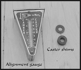
Now that you understand the locations and types of adjustments we will discuss some of the tools used to measure the settings. Camber is usually the easiest setting to measure since it is an angle that can be measured at the outside of one wheel. There are many special purpose levels made which can be held against the wheel hub or rim to measure the inclination or camber. They range in price from relatively cheap to very expensive. A general-purpose protractor/level seems suitable for this purpose and if you can find one that you can read repeatably to 0.1 degree it will work. Most are only readable to about one degree and you will find that this is not sensitive enough. Some digital levels available can be read to 0.1 degree and with a suitable fixture to set them against the rim they will work quite well. A cheaper alternative that works reasonably well is a two-foot roofing square, a small ruler calibrated in 32nds, and a little trigonometry. The camber tool shown in Figure 1was bought from J. C. Whitney and was relativelycheap. It measures the same things as the more expensive multiple tube models. Caster is quite difficult to measure directly. The best approach is to use one of the special-purpose level tools used to measure camber. These usually have a special caster scale which is used by turning the wheel a specific amount in one direction, measuring the tilt angle of the wheel on the caster scale, turning the wheel the same amount in the other direction, measuring again, and taking the difference of the two readings.
Toe can be measured (in inches) quite easily but it does involve a lot of squirming around on the ground. There are available tram gauges. This gauge is hooked around the back of the tire pair (front or rear), set to zero, and then hooked around the front of the tires. The toe is now read directly from a scale on the gauge. You can do the same thing with a tape measure. Measure between the inside sidewalls of the tires at the back and front and take the difference. Using either one of these techniques, you should measure as high up on the tire (towards halway up) as possible without the measuring tape touching any part of the car and at the same height front and rear. Since you cannot get halfway up the tire your reading will be a little short. Remember, you are trying to measure less than 1/16 of an inch in about 55 inches or about one part in a thousand. One other method is to hang a plumb bob from the front and rear of the sidewall on each tire, put a piece of tape on the ground, and mark the plumb bob center on the tape. After moving the car back out of the way, just measure between the marks. The tram gauge shown in Figure 2was bought from J. C. Whitney.
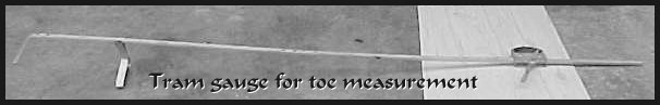
Figure 2. Toe gauge
To do all of this you need a place to work which ideally would be paved (smoothly), flat, and level with enough room to roll the car back and forth about 10-20 feet. If your workspace is not flat none of the adjustments can be made repeatably. If it is not level, the level based gauges will have a bias in their readings. Note that most garage floors slope one or two degrees from the back to the door which will confuse caster but not camber readings. Many driveways also slope to the outside edge and to the street which will confuse both readings. You can check this by measuring caster and camber and then turning the car around by backing into the same space. If the readings are different now, you do have slope but it is not an impossible situation.
The average of the two readings is the true setting and you simply adjust for the difference between this average and what you want. For instance if you measure camber of -.5 degrees, turn the car around, and read +.3 degrees then your camber on this wheel is -.1 degree. If you want to set-.5 degrees (-.4 degree change) and the car is still where you measured the +.3 degrees just reset it to -.1 degrees or make a -.4 degree change.
One more item which will make the job easier is a set of turntables. These are available commercially for a large pot of money but suitable ones for this purpose can be made cheaply. To make the turntables you need four pieces of sheet steel or aluminum about 12 inches square. If steel is used .040 thickness is sufficient but if you use aluminum get .060 material. Take a sheet, squirt a little chassis or wheel bearing grease on the center of it, and put another plate on top. Rub them together a little bit to spread the grease. Do the same to the other pair.
Now, why did you need these turntables? You will find that camber and caster adjustments are extremely difficult to reach or move with the car on the ground and the weight on the suspension. When you jack up the car and then lower it back on the ground the suspension will be bound up due to the changes in camber and toe when the suspension is at the end of travel. You can roll the car back and forth ten or twenty feet each time or just lower it onto the turntables which let the suspension move to its normal loaded position. Toe adjustments are also much easier when the wheels are on the turntables. One word of caution - do not attempt to drive the car off the turntables when they are under the rear tires. Push it off of them or you will probably grease your tires.
Inspection:
After you understand what the adjustments do and how to make and measure them there is one more matter. The car suspension must be in good shape with no worn out components. It doesn't do much good to carefully set the front toe to 1/16 if worn rack bushings, tie rod ends, or ball joints are allowing a 1/8 inch change in toe as you drive down the road.
Start at the front of the car and check each component. Bushings are usually checked by inspection. If the rubber looks decent, not frazzled and torn and hanging out, and the center bolt is in the center and not up against one side, the bushing is probably good. To check the upper ball joints, tie rod ends, and rack bushings jack up the front of the car and support it securely.[1] Grasp the tire firmly at the top and push/pull vigorously while listening for any clunking sounds and feeling for any free play. Do the same thing while grasping the front and back edge of the tires. If anything is noticed, watch the upper ball joint and outer tie rod end for relative motion. If you can see the upright[2] attached to the ball joint move while the suspension arm does not, your ball joint is bad. If the steering arm moves but the tie rod does not, the outer tie rod end is worn out. If the tie rod end moves sideways where it enters the rack, the rack bushing is worn out. This is especially common on the right side of 88s. If the tie rod moves slightly in and out of the rack the inner tie rod is probably worn. If you push hard enough there will always be some movement but what you are looking for is movement across a joint accompanied by a clicking/clunking noise. To check the lower ball joint lower the car back on the ground. Grasp the tire at the top and go through the shaking routine. If you feel or hear anything, watch for the upright moving while the lower suspension arm does not move. The lower ball joint will almost never show any free play when the car is jacked up since the spring has it pulled apart as far as possible.
To check the rear suspension, jack the back of the car up and support it securely. Inspect the bushings as before. Grasp the tire at the bottom, shake, and watch for movement in the lower ball joint (88s do not have a lower ball joint but use bushings instead). Grasp the tire at the sides, shake, and watch for play in the rod going from the rear upright to the sub-frame. This rod is only present on 84-87 models. On 88s just watch all of the bushings if any play is noticed. If any free play is noticed at any point in this inspection, the worn parts should be located and replaced before attempting alignment. You will probably find it difficult to get repeatable measurements the first time you try to adjust the alignment anyhow and worn components will make it impossible.
Now that you are ready to adjust the alignment you need to start with the correct adjustments. Some of the adjustments may interact with others so it is important that they be adjusted in the correct sequence. For instance changing the camber of the rear suspension on 84-87 models will produce large changes in toe so it is important that camber be set first.The correct sequence on the front suspension of the 84-87 model is caster, camber, and toe. The rear suspension has no caster adjustment so the sequence is camber, toe. The 88model front suspension should have the camber adjusted before the caster. One significance of this is that any time you change something higher in the sequence you should always check the following ones.
Measurement of caster:
As was mentioned before, about the only way to measure caster is with one of the specialized level type of tools. The usual sequence is to turn the wheels so they are at a specified angle to the car and measure the tilt of the wheel on the caster scale, then turn the wheels to the same angle in the opposite direction and measure again. The difference in the readings is the caster.
If you are using a digital level, this technique will give the same results:
Left caster = 2 * (Left out - Left in)
Right caster = 2 * (Right out - Right in)
Measurement of camber:
Camber is measured by applying one of the special level tools to the center hub of the wheel or the rim of the wheel and reading the camber scale. If there is not a sufficiently large or flat enough space at the center of the wheel or you are using a digital level you will need to make an adapter, which can be as simple as a piece of 2x4 with the middle trimmed out, which will reach from one edge of the wheel rim to the other. Do not use the actual lip of the rim as this is not always flat due to road damage. There is usually a flat surface on the outer edge of the rim which is satisfactory. Position this firmly on the wheel and apply the gauge or level to get a reading. This same adapter will be required for the caster measurements previously described.
If you do not have one of these tools a simple roofing square and ruler can be used. Position the square so the short arm is flat on the ground and the long are is vertical and centered over the wheel. Slide the square up against the tire sidewall and notice the point of contact. If it is on the upper part of the tire you have positive camber and if it is on the lower part you have negative camber. Measure the distance from the point of contact to the same part of the tire on the other side and call this distance "R". Measure the separation of the tire from the square to this second point and call this distance "Y".
Camber = arc tan (Y/R)
which most scientific calculators will determine for you.
Measurement of toe:
Toe can be measured with a tram gauge by positioning the gauge behind the tires, setting the reading to zero, moving the gauge to the front of the tires, and reading the toe. Watch the point of contact on the tire of the gauge arms. Many tires have sidewall decorations such as raised letters. If an arm is on one these at one time and not another, wildly different and inaccurate readings can result. Also any time the toe is changed the gauge must be rezeroed.
If you do not have a tram gauge, a simple tape measure will work. Simply measure the distance from the inner sidewall of one wheel to the other at the back and the front. The difference is total toe and if the back measurement is greater you have toe-in. The same precautions about sidewall protrusions and re-measurement as stated for the tram gauge apply here also.
Measurementof the car alignment:
The following is a complete procedure for measuring caster and camber. You may not need to do everything listed but if this is the first time to do this it is a good idea to go through the whole routine. Because the caster and camber adjustments are difficult to reach or change with the car sitting on the ground the best approach is to measure both with the car on the ground and write the results down, then jack up the car and make the desired changes.
Adjustment of front suspension, caster and camber:
The caster and camber of the 84-87 model is adjusted differently than the 88 model so they will be described separately. The toe adjustment is the same on both models so they will be described as one. Refer to the pictures for the location of each adjustment.
Important note: Remember that the camber and caster measurements made while you are making the adjustments are made before and after making a change for the purpose of measuring the change and are not by any means the actual finished measurements. They will usually be quite different from what you measured with the car sitting on the ground, Remember only the differences count here.
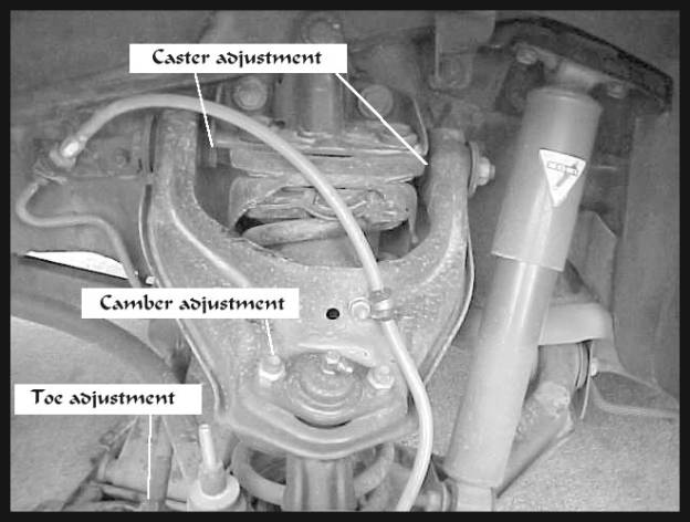
Caster on the 84-87 is controlled by a matched pair of serrated washers with a constant total thickness.The set originally installed on the car are usually equal in thickness. There is a thicker/thinner pair available from the dealer to allow adjustment if your present setting is not correct or what you want. To change the washers do this:
Camber on the original ball joints of the 84-87 suspension was controlled by the position of the upper ball joint. The ball joint could be unbolted , turned around, and bolted back down for one degree more positive camber. Replacement ball joints usually have slotted mounting holes so that the mounting bolts can be loosened and the ball joint slid back and forth (sliding towards center of car makes camber more negative) to change the camber in smaller increments. The mounting holes can also be slotted to achieve the same results with the original ball joints. In any case do not move the ball joint so far inboard that it hits the spring. Before trying to adjust anything, measure the camber and write it down. After you have made your adjustment measure the camber again to see if the change is the amount you wanted. Some tools will allow you to measure the camber as you are making the change which is handy if you have one of the slotted variations. However, the reading will probably change a small amount when the ball joint is tightened back down.
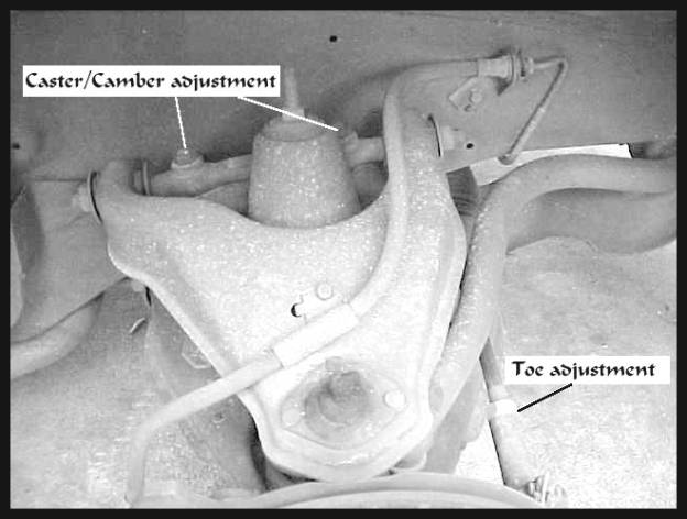
Figure 4. 88 Front Suspension, right side
On the 88 model the caster and camber are both controlled by the position of the pivot arm on the upper suspension arm. It is mounted to the crossmember by a pair of bolts in slotted holes. To adjust camber and caster follow these steps:
Adjustment of the front suspension toe:
The toe adjustment is made at the outer tie rod end on each side of the car. After you have measured the toe (do this AFTER caster and camber are properly set) you adjust the toe by loosening the locknut on the tie rod at the outer end and twisting the tie rod itself to screw it into the rod end (more toe in) or out of the rod end (more toe out). Be careful to adjust each side by the same amount, both in or both out. One quarter turn of each rod is usually good for a change of 1/16 inch to 1/8inch in toe. After you have adjusted and measured the toe drive the car down the road and note the steering wheel position. If it is not centered you will need to make another adjustment. This time you need to adjust each side by exactly the same amount in opposite directions, one side in and one side out. After everything is correct, be sure to retighten the locknut.
Adjustment of the rear suspension camber:
Camber is adjusted in the same manner on all models. The camber adjustment is the lower of the two strut mounting bolts as shown in Figures 6 and 7. There is an unavailable part which will make this job much easier as in changing almost impossible to "nothing to it". The camber adjusting bolt as shown in Figure 5 is found only on the front struts of 1980 model GM "X" cars such as Citation, Phoenix, Omega, and Skylark. They are not available as replacement parts so a trip to your local "Pick-A-Part" with a lug wrench and two 24mm wrenches is well worth while. The bolt has a built-in off center washer which bears against stops on the struts so that turning the bolt head moves the strut back and forth and changes the camber. Not all struts have the stops so if you have some of these you are just out of luck.
To set the camber follow these steps:
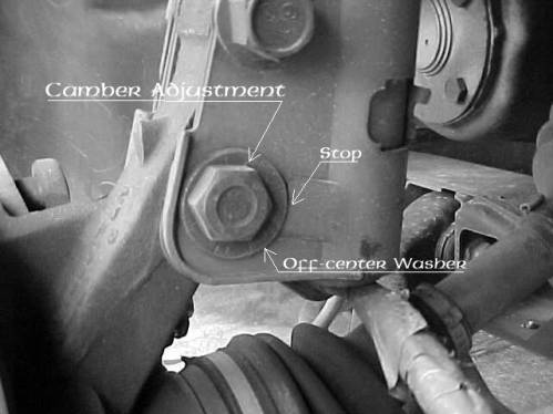
Figure 5. Camber adjustment
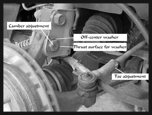
Figure 6. 84-87 Rear Suspension, left side
Adjustment of the rear suspension toe, 84-87 model:
The rear toe adjustment is similar to the front toe and done exactly the same way. Once again, be very careful to change each side by the same amount. If you have changed the camber at all the toe will definitely need resetting on these cars. When finished drive down the road with the steering wheel straight and see if the car goes straight. If it drifts to one side or the other, the rod adjustments are not matched and must be adjusted in a manner similar to centering the steering wheel in the front. If the car drifts to the right, this means the left rear tie rod is too long and the right is too short. Both must be adjusted exactly the same amount in opposite directions to correct the problem. If the car drifts to the left, this means the left rear tie rod is too short and the right is too long.
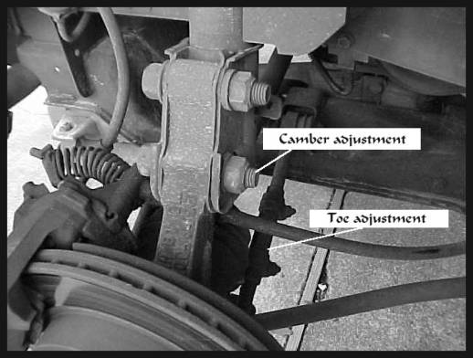
Figure 7. 88 Rear Suspension, right side
Adjustment of the rear suspension toe, 88model:
The rear toe adjustment is similar to the front toe although the adjustment is done a little differently. The front lower suspension arm has a threaded sleeve in its middle and this is the adjustment point. Loosen the two clamp bolts before attempting to turn the sleeve. The best way to turn the sleeve is with a drum brake type adjusting tool inserted in the side of the sleeve. Anything that clamps onto the sleeve, such as vicegrip pliers, will cause to be difficult to turn. Once again, be very careful to change each side by the same amount. When finished drive down the road with the steering wheel straight and see if the car goes straight. If it drifts to one side or the other, the rod adjustments are not matched and must be adjusted in a manner similar to centering the steering wheel in the front.
If the car drifts to the left, this means the left rear tie rod is too long and the right is too short. Both must be adjusted exactly the same amount in opposite directions to correct the problem. If the car drifts to the right, this means the left rear tie rod is too short and the right is too long. After making all of the adjustments, be sure to re-tighten the clamp bolts. These can be repositioned before tightening to make the job easier.
Factory specified alignment settings for 84-87 models (from the 1987 MVMA Specifications)
Front camber+0.5degrees(I use -0.7degrees)
Front caster+5.0degrees
Front toe+0.15degrees(this is approximately equivalent to 1/16inch toe-in)
Rear camber-1.0degrees
Rear toe+0.15degrees(this is approximately equivalent to 1/16inch toe-in)
Factory specified alignment settings for 88 model (from the 1988 MVMA Specifications)
Front camber+0.0degrees(I use -0.5degrees)
Front caster+3.0degrees
Front toe+0.15degrees(this is approximately equivalent to 1/16inch toe-in)
Rear camber-1.0degrees
Rear toe+0.15degrees(this is approximately equivalent to 1/16inch toe-in)
[1] Securely means setting on jackstands on both sides of the car in such a manner that vigorous pushing sideways ofthe car does not move the car or make the stands tilt. When supported on a single jack the car can tilt and then slide off of the jack when pushed sideways.
[2] The upright is the cast iron piece mounted between the ball joints which has the axle and steering arm attached.
If you would like to download your own copy as a Word file, here it is: Home_Alignment.doc