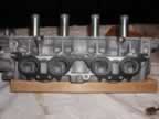
5S-FE Cylinder Head Porting & Polishing
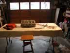
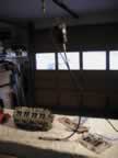
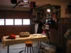
In porting & polishing a cylinder, some of the more obvious things can easily be overlooked. For example, be sure to have a well lit and comfortable work area. You will be turning the head in all sorts of directions and trying to get good looks from different angles. I setup the following environment to work in:
I used a Dremel rotary tool that has a flexible shaft. Top free-running speed of the unit is 22,000RPM. Whatever you use, be careful of the rotational speed as the aluminum head cuts fairly easily. As far as bits, I used carbide tipped bits as well as a porting & polishing kit from Standard Abrasives. Their kit is unique in the fact that it comes with a finishing tool called a cross-buff. This allows you to get a mirror finish on the exhaust ports. Their kit is pretty complete. It is part number 260001 and is available from Summit Racing for about $40 (Link here)
I shouldn't have to mention the real obvious...eye protection. You will have metal chips flying everywhere! And when you're polishing, a mask is definitely a good idea. Aluminum powder tastes lousy!
Before starting this project, I tried to educate myself as much as possible. Talk to people that have done this before. I have a fairly new machine shop nearby. The guys there were great for looking at the head and suggesting where to concentrate my efforts. Another good source of info is a document from Standard Abrasives: Their web site is here or you can download the PDF document from here. Another thing to try to get information is a Google search on "DIY Porting" Another good source of info was a video from Standard Abrasives (I should get some kickback from Standard Abrasives for how much I'm mentioning them!). The video is called "Power Porting" and is availble on Summit Racing for about $21 (Link here).
Another step you may want to take is to get the head flow tested. I had this done so I could measure the work I am doing. The pre-port flow report is here. For the post port & polish, click here. The specs on the Ferrea valves are as follows:
Intake valves: 33mm (head diameter) X 97.5mm (stem length) with a 6mm diameter stem
Exhaust valves: 28mm (head diameter) X 98.5mm (stem length) with a 6mm diameter stemAs part of the head modifications, I am also replacing the stock camshafts with ones modified by Crower Cams. The spec card that was included can be seen here. Other components of the head mod include an adjustable fuel pressure regulator and fuel pump. These were installed during the Engine Rebuild #2 portion of the 'project'.
Porting
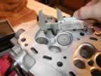
The first step was to match the size of the intake ports to the size of the intake manifold gasket. To do this, take the gasket and fix it against the head. Then mark the area of the head that extends within the gasket openings. This is the area to be removed.
In the above pictures, you can see Toyota did a pretty good job of matching the size of the ports to the size of the gaskets naturally in their casting. Only a small amount of metal had to be removed. Whatever you grind away to open the port, be sure to blend that into the rest of the port over a 1 - 2 inch area.
I didn't gasket match the exhaust side. The basic rule is you never want an upstream bump. Therefore, if anything, you will want the exhaust port on the head to be smaller than the exhaust manifold.
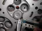
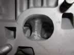
Next was to check the size of the throat compared to the size of the valve head. It is supposed to be 85% smaller than the size of the valve head.
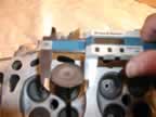
The first picture above is measuring the port throat. I measured mine at 27.64mm. The second picture was measuring the valve head, which was 31.96mm. The throat is 86% smaller. No need to do any work here!
Next was on to finding parts of the port that should be cut away to increase and smooth the flow. To accomplish this, the best tool is your finger. Feel around inside the port and look for sharp edges are bad transitions.
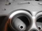
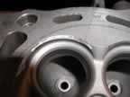
The first area I found of concern was the short side radius on the intake and exhaust ports. These had rather sharp edges to them that would cause a significant amount of turbulence. Although difficult to access, take your time and put a nice smooth radius on these. Be sure to turn the head a lot to get at it from different angles. This really helps to get consistency from port to port.
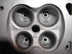
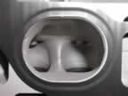
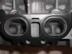
Another area to concentrate on were the valve bosses. These are the bumps that hold the valve guides in place:
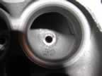
I landed up grinding these down smooth. I know these help support the valve guides and I'm sure I'd get some arguments here, but the portion of the boss that stuck out in the area of the port was minimal when looking at the entire guide, but substantial when looking at the port. If the valve fails a little earlier, then so be it. I wanted the extra flow now. To be honest, everyone that I asked thought it wouldn't make a difference in the lifetime of the valve.
In each port there are splitters that either seperate or join two sources of flow (on the intake or exhaust side, respectively). These splitters were "rough around the edges" so I almost 'knife-edged' them. I say almost because I tried to leave a slight radius to it so it wouldn't change the flow characteristics too much:
First picture is stock. The last three are after working them.
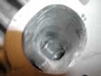
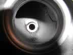
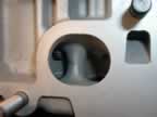
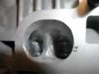
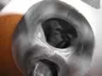
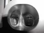
One of the final steps in porting was to open up the shoulder, or shroud, around the valve head. The reason for this is because I am going to replace my stock valves with Ferrea oversized valves to allow for more flow. With the oversized valves at 32.96mm (an extra 1mm), I will be looking at roughly a 84% ratio between the port throat and the valve head. Still very close to the desired 85% ratio.
First two pictures show the shroud stock. Third is after pushing the shoulder back a little bit. The purpose for this is to allow air to flow more smoothly when going past the valve head. If the clearance is tight, more turbulence will be generated, resulting in loss of flow. If you do this, be sure to put an old valve in first to protect the valve seat!!! The last two pictures show the clearance between the valve and the shoulder, stock and after cutting it away.
Another note on this: Remove as little material as possible. The removed material will lower the compression ratio and result in a loss of power. The main point is to remove only what is necessary.
Polishing
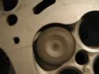
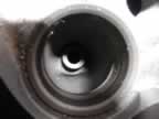
The last step in this process was to polish the exhaust ports. This is where the Standard Abrsives kit is great. With the selection of flapper wheels and Cross Buffs, I was able to get a mirror finish on the exhaust port runners.
Above is the final progression from rough to smooth using the sanding bits, flap wheels and Cross Buffs. The rough surface was left after using the carbide tipped bits and stones. This will get you the basic shape you want. Then you polish it smooth to finish it off.
It is important to get a finish as smooth as possible on the exhaust side. This is becuase it will keep carbon from building up and restricting flow later on.
Something I was not aware of when I polished was that you should use a light oil with the Cross Buffs. the finish comes out even better with it. Mine came out great, but I destroyed all 4 Cross Buffs that came in the kit.
31-Jan-2003 : The head is now back at the machine shop awaiting the post port flow test, a good cleaning and a 5-angle valve job with new custom Ferrea 1mm oversized valves and new stock Toyota springs. Along with these changes are Crower reground camshafts, Fidanza adjustable cam gear and a powder coated valve cover. I also asked the shop to shave of enough of the head to increase the compression ratio back to 9.0 from 8.5. With the dished pistons, I'm hoping this won't be a problem...but they will let me know. I supplied them with all the info on my pistons I got from JE.
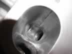
1-Feb-2003: Time to install the new head! Lands up the dish depth could not be determined from the JE paperwork. But that's not too important now. I discovered a larger problem when I went to install the newly modified head. The JE pistons are trash. The skirts are scratched beyond a usable state. They need to be replaced before the engine can be buttoned up. New pistons and rings will need to be installed. The cylinders will need to be honed so the new rings will seat properly.
Since we are getting off the subject of the cylinder head, click this link to follow the engine issues.