Day 1 | Index | Day 3
1996 Camry 5S-FE Turbo Install
|
Day 2
|
Picture 1 |
Picture 2 |
Picture 3 |
Picture 4 |
Picture 5 |
Today, day 2, was a day of issues... First task was to replace the cylinder
head. The timing marks on the cam shafts are absolutely horrible! There were
multiple marks and the shop manual did not make it clear which marks should
be used. The process of getting the timing correct took a good 11/2 to 2 hours.
Once that was done (and rechecked the compression on each of the cylinders)
we moved on. We got the intake manifold installed and closed up the front of
the engine (from changing the timing belt & water pump). We tried to test
fit the turbo and manifold and had a few surprises waiting for us!
Problems:
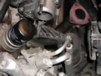
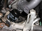
- As shown in figure Picture 1 above, the oil filter cannot be removed after
turbo down pipe is installed. Also the oil dipstick cannot be accessed with
the turbo in place.
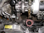
- Depicted in Pictures 1 and 2 is the large variance between the turbo exhaust
port and the exhaust pipe going to the next catalytic converter. Attached
to the supplied down pipe would need to be almost an "S" shaped
pipe to mate the two.
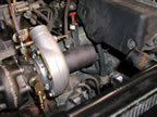
- Picture 3 shows the intake pipe of the turbo is almost butted up against
the cruise control. This allows virtually no room for the 90° elbow. Also
shown is the problem with the automatic transmission dipstick/filler tube.
The dipstick needed to be bent back quite a bit to create space for the turbo
intake pipe.
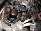
- Picture 4 shows again the tight fit between the exhaust port of the turbo
and the oil filter. Also, the turbo does not allow access to the oil dipstick.
- Picture 5 illustrates how the flange for the down pipe does not clear the
oil filter and therefore cannot be installed without modifying the oil filter
position.
To successfully install the turbo charger on the 1996 Camry LE 5S-FE equipped
car, the following is a list of requirements:
- The oil cooler located below the oil filter must be removed. The relief
valve tube that the oil filter gets threaded onto must be replaced with a
shorter one. Removing the cooler allows the oil filter to drop roughly 2.5".
This will create the needed clearance to allow changing the filter. If necessary,
a secondary air-cooled oil cooler can be installed.
- The included down pipe cannot be used unless it can be bent further to clear
the air condition lines and the front engine mount.
- The intake pipe must be cut shorter to create the necessary clearance to
avoid the cruise control unit.
- The oil dipstick tube must be reoriented to allow removal and insertion.
Otherwise the turbo blocks access to it.
- The oil pressure sensor is mounted on the included T. This T has NPT threads
on it and the head has metric threads. It was recommended to 'dress' or file
down the threads to provide the necessary clearance. A better idea would be
to either provide an adapter that provides the needed conversion between metric
and NPT threads, or to braze a metric fitting onto the T (the latter is what
we landed up doing).
- There are multiple electrical connectors that needed to be relocated due
to space requirements of the turbo and pipes.
- Support brackets should be included with the kit or fabricated to support
the intermediate pipe.
- As a general suggestion, the oil return line should be installed toward
the rear of the oil pan, closer to where the drain is on the turbo. Currently,
there is a long horizontal piece to connect the turbo drain to the oil pan
tube that will cause some oil puddling. We chose to install a right-angle
elbow to turn the oil drain fitting on the turbo to direct the oil return
tube toward the front of the engine where the oil pan's return tube is.